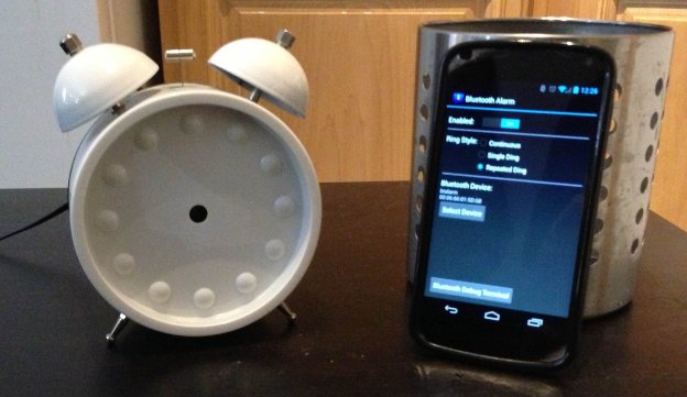
I’ve woken many mornings to a blaring square-wave-through-overdriven-8Ω-speaker alarm tone dragging me back to consciousness from the warm depths of sleep.
Searching for a better alarm, I bought an analog-face alarm clock with a double-bell ringer and found the alarm sound to be crisp and clear. However, the clock wasn’t perfect: I had to remember to set it every evening, and the second hand tick-tocked all night long.
I decided to modify the clock so it could be controlled by my Android phone. I stripped out the clock mechanism and added a Bluetooth module, then wrote an Android app to ding the clock ringer when triggered by the built-in Android alarm clock app.
I’ve been happy with it so far—read on to see how I built it.
Hardware
Alarm Clock
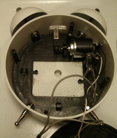 I used an alarm clock with double-bell mechanical ringer (cost: about $10).
The clock hands are advanced by what appears to be a stepper motor winding built into the mechanism, which is driven by an epoxy-potted timing circuit.
The clock is set by turning knobs to move the hour, minute, and alarm hands.
When the alarm time is reached, an electric circuit is completed by mechanical contact, which turns on a small DC motor to strike the alarm bells—no electronics here! The DC motor runs from two 1.5V AA batteries in parallel.
Bluetooth Module
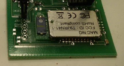
For the Bluetooth interface, I used a Roving Networks RN-41 Bluetooth module.
[Update 1/3/2015: There are fuller-featured and less expensive modules available now. For an idea of what’s out there now, take a look at what we’ve included in the Octopart Common Parts Library.]
The module is a fully integrated solution which provides everything needed for a Bluetooth Serial Port Profile (SPP) link. Bluetooth SPP emulates a serial port: data sent over the Bluetooth link is passed through to the UART pins. The module also provides several general purpose I/O (GPIO) pins which are controlled by entering a command mode. The GPIO functionality was exactly what I needed for this project.
For a previous project, I had designed a custom PCB for the RN-41 that I was able to re-use as a breakout board. GPIO 3 was the most accessible on my PCB so I used it to control the ringer motor.
The RN-41 requires a 3.3V supply. I had a 5V wall adapter handy so I used it along with a 3.3V LDO regulator to power the RN-41.
RN-41 Command Mode
The Roving Networks Advanced User Manual
[update 1/3/2015: unfortunately the page seems to have been removed]
documents the command set for controlling the Bluetooth module.
Sending $$$ causes the module to enter command mode where it will interpret received data as configuration commands rather than passing the data through to the UART.
The module stays in command mode until it sees the command ---.
Two things to note: every command except $$$ is followed by a carriage return character, and,
by default, it is only possible to enter command mode within 60 seconds of cycling power.
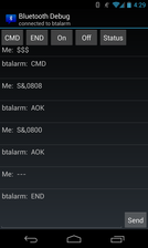
To test the Bluetooth link, I used the Bluetooth SPP Android app. After pairing with the RN-41 Bluetooth module, I used the Bluetooth SPP app to confirm that it responded to commands as expected, then modified some configuration settings.
Here are the commands I used:
1 2 3 4 5 6 7 8 | |
Motor Switching
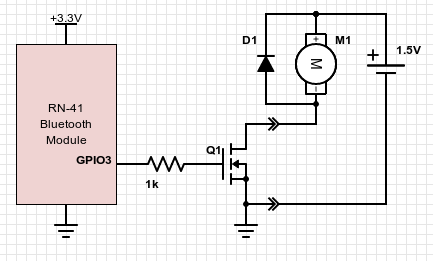
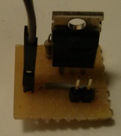 First, I soldered a 1N4004 diode at the motor terminals for flyback suppression.
I didn’t have any test gear handy to see how much current the motor draws. Since it was powered by two AA batteries in parallel, it seemed safe to assume that it could easily require up to a couple hundred milliamps.
I tried using a MPS2222A NPN transistor to switch the motor. I found that the motor turned on when forcing the base high through a resistor to +3.3V but not when controlled by the RN-41 GPIO pin. I suspect the RN-41 GPIO pin was unable to source enough current to drive the transistor into saturation. However, the datasheet didn’t specify a current limit for the pins and without test gear it wasn’t worth speculating.
I swapped the MPS2222A for an International Rectifier n-channel power FET with 3.3V-tolerant gate threshold. Success! The Bluetooth module turned on the ringer motor.
Android application
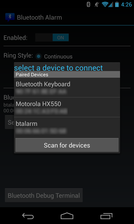 This was my first time creating an Android app so I started out by
installing the SDK
and working through the
Building Your First App
example in the Android developer docs.
The whole process turned out to be very easy—I was running a “Hello, World” app on my phone within a couple of hours.
Quite a contrast to the development tools for some of the microcontroller and FPGA platforms I’ve used in the past!
For the most part, I tested using an actual phone. While it’s nice that the Android emulator is available, I found it to be very sluggish.
The Android SDK comes with a Bluetooth Chat sample project, which demonstrates how to create a background service in a separate thread to handle Bluetooth communications. To communicate with the RN-41 module, I found that I needed to change the Bluetooth UUID to the proper value for an SPP connection. I converted the chat app into a debug terminal, allowing me to send arbitrary commands to the RN-41 or press shortcut buttons for command mode and GPIO control.
 I ran into an error when trying to run the Android example:
getActionBar() call returning null.
A StackOverflow search provided a fix which involved a
change to the AndroidManifest.xml file
for the project.
I thought it would be elegant to trigger the Bluetooth alarm clock from the built-in Nexus 4 Android 4.2 alarm clock so,
ideally, I wanted to find a way to intercept alarm events from the system alarm clock.
I found a post that pointed me in the right direction.
The alarm event can be captured by creating a BroadcastReceiver to receive the com.android.deskclock.ALARM_ALERT action.
Note that alarm events from other alarm clocks (older Android builds, manufacturer/carrier builds, third party apps) will use
different actions.
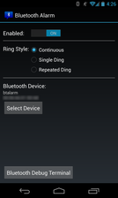 My alarm app is implemented using a background service that registers the BroadcastReceiver to listen for alarm events and starts the ringer when an event occurs.
The service is loaded when the app is installed or the phone is powered up.
Since I wanted to support a “repeated ding” ringer style, I also created a separate alarm ringer background service thread
to support sending a timed pattern of Bluetooth commands, with pauses.
I wanted to be able to set configuration options to enable/disable the alarm, change the ringer style, and save the selected Bluetooth device so I created the appropriate UI controls and used the Android SharedPreferences API to store the settings.
Full source for the Android application can be found at github.com/qqrs/btalarm.
Acknowledgments
This was a project I worked on at Hacker School. Hacker School is a free three-month self-directed learning environment that has been described as being “like a writers’ retreat for programmers.”
Many thanks to @leocadiotine for repeatedly offering expert guidance in navigating the intricacies of the Android APIs.